A Perspective on Finger Bars
Finger bars or more specifically workpiece engagement tools for transfer fed stamping dies, are integral to the process development task. Understanding the options is vital to developing the best manufacturing process for a given stamping.
The function of finger bars is to attach the workpiece to the transfer mechanism so that it can move the workpiece from one station to the next. Simple enough until some of the requirements are examined. For example, the attachment may need to occur in less than 1/10 of a second. The connection may need to be made by friction between the fingers and the workpiece without marring either surface of the stamping. The center of gravity and or mass may be offset from the finger attach point. The workpiece may need to be rotated about an axis perpendicular to the transfer or transferred a varying amount relative to the other workpieces being transferred.
![]() Three Axis Transfers
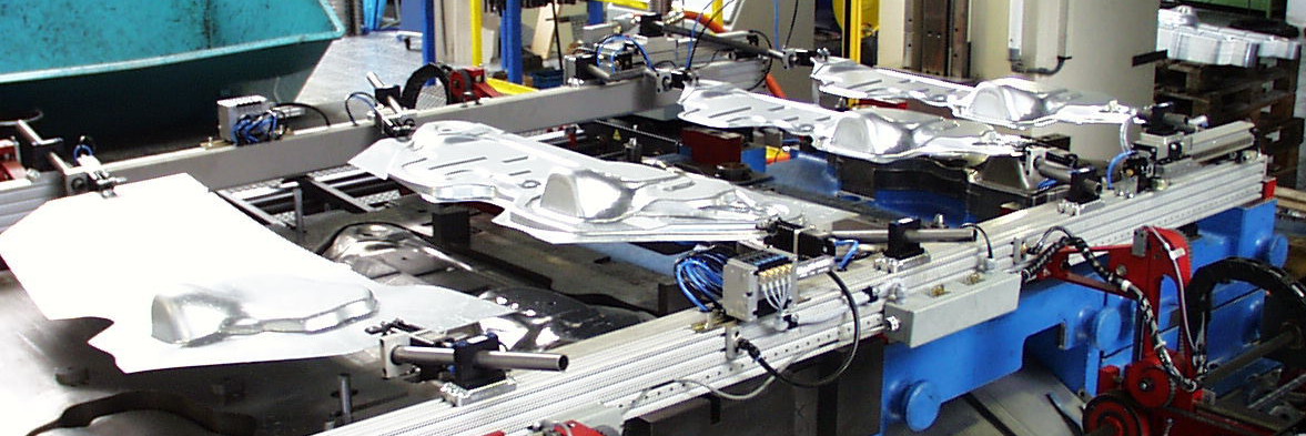
Three Axis Transfers
Three axis transfers are the most versatile. The first movement brings the fingers horizontally until they engage the workpiece. The second move lifts the workpieces up away from the die stations and out of the gauges. The third move repositions the workpieces over the subsequent stations. The fourth move lowers the workpieces onto the die stations and into the gauges. The fifth move disengages the fingers from the workpieces. Finally, the last move returns the finger bars to the start position. The return stroke can generally occur during the press cycle through the bottom. Variations of this path are possible with servo systems such as engaging the workpiece from the top rather than the side.
The simplest finger bars pick up a rigid workpiece by encapsulating the part. Rigid fingers surround the workpiece, usually in all three axes. The workpiece can then be transferred. The workpiece must be presented to the finger bars with enough clearance for the fingers to engage the workpiece. Typically, about an inch of clearance is required. One consideration to keep in mind is the angle moment of contact. A shallow angle of contact is a common problem. Fingers can move relative to the workpiece as speed increases. When this happens, what seemed like a good fit could become a marginal fit and a marginal fit could let go of the workpiece.
Finger bars that employ grippers are used to solve several problems. Flexible workpieces can be tensioned between the front and rear grippers to prevent the workpiece from slipping out of the fingers. A workpiece that presents a poor angular moment of contact may need to be gripped, especially if the center of mass is offset from the finger. Grippers generally require more clearance than the encapsulation type fingers but with the large selection of commercially available grippers, finger clearance problems are minimized. Be aware that grippers take time to activate and therefore they increase cycle time. Grippers can be activated ahead of the end of the transfer clamping stroke to compensate for latency, but a short dwell period simplifies the timing development. Likewise, grippers can be released ahead of the start of the unclamp stroke to compensate for latency.
Plastic fingers can be used to prevent marking the workpiece. Plastic or rubber can also provide additional grip for gripper type fingers. Nylon is a hard-durable plastic that works well for lining finger grippers. While Nylon is durable it is not compliant and therefore does not grip well. For painted and/or embossed material, neoprene works well. It is not as durable as nylon but is available in varying degrees of hardness to meet the desired properties. The hardness is measured in units called durometer. A low durometer works well for painted and embossed sheet metal when grip is important and surface marring is undesirable but is less durable. A harder durometer grade would suit painted non-embossed material and is more durable.
Short rigid workpieces may be transferred from one side. This method will generally require grippers to hold workpiece orientation during the transfer movements. This can reduce the amount of mechanism required and therefore reduce costs. Die changes are also simplified and operator visibility is also improved using a one-sided transfer.
Workpiece rotation or reorientation can be accomplished in several ways. For rotations about an axis perpendicular to the finger bars, rotating fingers can be used. Actuation of these fingers can be by pneumatic rotary actuators also known as rotary air cylinders, servo motors, and rack and gear drive. Because this rotation can occur during the transfer move timing is generally sufficient to allow the use of a simple pneumatic rotary actuator. Another common practice is simply to lower the workpiece onto the station and allow gravity to orient the workpiece. The die can also contain the mechanism to rotate the workpiece. When the die rotates the workpiece, it can be made to stay in the new orientation or brought back to the as loaded orientation.
In addition to rotating a workpiece, fingers can move a workpiece linearly along the pitch axis. This may be beneficial to allow the last workpiece to remain in the press for unloading if the press windows are too small to allow the transfer bars to open up. Another reason is to minimize the space required between die stations to fit smaller beds. For example, the draw form station is commonly larger than subsequent stations. A stamping can be transferred further out of the draw station, while the transfer pitch suits the subsequent stations, using an additional linear pitch motion in the finger bar apparatus. There are several ways to achieve a linear move and one of the simplest is with a pneumatic linear actuator.
![]()
Bridge Type Two Axis Transfers
A bridge-type transfer parts between stations, moves over the workpiece drops to engage it, lifts the workpiece and moves it to the next station where it drops in off and returns to the park position between stations. Bridge finger bars are commonly used on large stampings. The bridge provides greater strength than the cantilevered type finger bars discussed above. The workpiece can also be supported in more places using a bridge type finger bar. Access to the workpiece is typically from above and not from the sides. This allows more options for the die such as cams, heels and form steels. Typically, vacuum cups are employed for lifting the workpiece.
Vacuum cups are able to pull perpendicular to the surface they are attached to. Atmospheric pressure is about 14.7 PSI and since the vacuum measurement is really the difference between atmospheric pressure and the pressure in the vacuum passage the maximum vacuum is 14.7 PSI. Compressed air vacuum generators are able to efficiently produce about 10 PSI of vacuum. Therefore 10 PSI of vacuum is 2/3rds of the maximum possible, which is a good practical value to use. So, a two-inch diameter vacuum cup contains about six square inches which at 10 PSI of vacuum can lift about 60 pounds. The ability of a vacuum cup to impart force parallel to the surface it contacts is dependant on the friction between the vacuum cup and the stamping. This friction can vary greatly with sheet metal surface conditions and various oils and drawing compounds. For this reason, a rigid finger to provide force to the workpiece in this direction may be required to achieve the desired acceleration/deceleration.
Magnet grippers are a good alternative to vacuum cups for magnetic workpieces. These grippers have strong permanent magnets encased in durable plastic. The release is achieved by air pressure pulling the magnet away from the plastic face. These can be more durable than vacuum cups and will work on irregular and/or perforated parts.
Lift and Carry Walking Beam Transfers
As the name implies the Lift and Carry transfer bars engage the workpiece from below lifting it and then moving it to the next station where it drops it and returns to the start position. The return stroke can generally occur during the press cycle through the bottom. A lift and carry transfer also known as a walking beam transfer has different considerations. By its nature, the workpiece must be accessed from below. This has the advantage of stability and quick cycle times without a long press stroke. The obvious disadvantage is gaps in the lower die steels. Gaps in the die steels can be compensated for in a couple of ways. The finger bar can be very narrow which can allow the workpiece to be formed across the gap without a significant impact. Handoff stations can change the relative location of the gap thereby allowing work to be done to the entire workpiece. Gripping the workpiece is impractical although not impossible in a lift and carry transfer. Round tubular workpieces with seam location requirements can roll so that the seam location is out of tolerance. This can be minimized with an accurate transfer movement as well as with a quick transfer movement which has less impact due to the inertia of the workpiece.
![]() Workpiece Sensing
Workpiece Sensing
Sensing the workpiece in the fingers has advantages over in die sensing although it is much more difficult given the dynamics of the moving mechanism and workpiece. While in die sensing is important and more stable, sensing the stamping in the fingers will signal the press, much sooner, that a problem exists. It is much better to detect a stamping that stays in a draw cavity before the second one is stamped than after. Proximity switches are commonly used for finger part sensing. One problem with proximity switches is the limited sensing range. A proximity switch set near the limit of its range can cause nuisance faults. A proximity switch set too close to the part can be easily damaged. Infrared light, visible light and laser sensors, with their longer detection ranges can reduce nuisance faults and the damage caused by the need to set proximity sensors so close to the workpiece. The longer-range sensing can also indicate a workpiece present when that is not true. A vast array of switches is available for workpiece sensing. When selecting the best switch to use keep in mind the sensing range required for the amount of control over the workpiece that the fingers have and the environment that the switches will be subjected to.
In Die Gauging for the Workpiece
A quick word about part location gauges. They need to be made as big as possible with as much lead as possible. As the cycle speeds up the mechanical system flex, workpiece flex, mechanical vibration, workpiece vibration, and latency following errors all increase. Give yourself as much chance as possible and make the gauges as large as possible. And if the job ever needs to be run by hand the production personnel will appreciate it.
![]() Demystifying the Transfer Process
Demystifying the Transfer Process
One common misconception is that a common transfer height must exist throughout the die. Another common misconception is that a common point on the workpiece must exist throughout the die. Neither is true. What is true is that the workpiece that is picked up in one station will be dropped off in the next station in the same relative position. This does not take into account articulated fingers. The location of workpiece engagement can be different in each station. The workpiece can be modified completely in any station because each finger will only engage one version of the workpiece so it can be designed to fit that particular workpiece in its current stage. The workpiece can change height in any station because each finger will only engage the workpiece at that height. The workpiece can change orientation in any station because each finger will only engage the workpiece at that orientation. So, feel free to drop parts and reorient parts to suit the process.
Summary
Understanding the various types of transfers for automating the stamping process is important. So is understanding the role of the finger bars, the dynamics of the transfer mechanism, component motion timing, workpiece dynamics, types of products available for transfer automation and many other factors. I’ve discussed some of the key elements of automating the stamping process but certainly not all. Please feel free to contact me with your challenges. I’d be happy to help.
Tim Launiere
DieBotics
© 12/1/2019